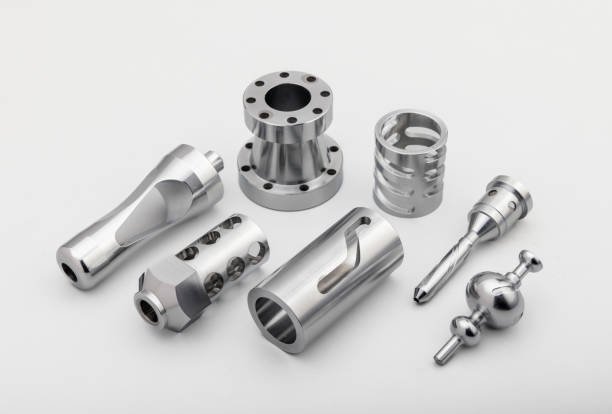
The CNC (Computer Numerical Control) machine is a pivotal component in modern manufacturing, blending precision engineering with cutting-edge technology. Renowned for its capacity to execute intricate tasks with unmatched accuracy and efficiency, the CNC machine has transformed industries across the board – from automotive and aerospace to woodworking and electronics.
By translating digital blueprints into physical reality, CNC machines have become indispensable assets for fabricating complex components swiftly and consistently. Today, MaTec Vietnam will explore parts of a CNC Machine and learn how to clean and maintain them.
Parts of a CNC Machine
Firstly, MaTec Vietnam will separate them into two categories: Control System and Machine System.
Control System
In parts of a CNC machine, the control system manages information, inputs, and outputs for the CNC machine. 4 parts of the control system are:
Control panel
Within the control panel are the input device, display unit, keyboard, and additional control buttons, facilitating operators’ interaction with the CNC machine. Typically, the control panel is affixed to the CNC machine via an extendable arm, enabling the operator to position the screen conveniently.
Input device
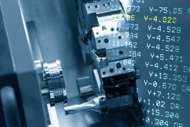
The input device of a CNC machine serves as the conduit through which CNC programs are transferred into the machine. This device may comprise a keyboard for direct entry of G-code commands, a USB flash drive for transferring a preprogrammed file from another computer, or wireless communication for downloading programs from another computer via the local network.
Machine Control Unit (MCU)
The MCU, or machine control unit, encompasses the electronic hardware and software responsible for interpreting the G-code provided by the input device. It translates this code into instructions executable by the tool drivers to execute the intended machining operations. As one of the pivotal components of a CNC machine, the MCU plays a critical role in converting G-code coordinates into movements executed by servo motors across the machine’s various axes.
Additionally, it interprets feedback sensor data to ensure that the tool attains the expected position post-movement. Moreover, the MCU oversees operations such as tool changes and coolant activation as dictated by the G-code.
Feedback system
Even with the precision of the driving system, employing a closed-loop control system is often essential. This ensures that after the machine moves a mechanical component to a designated position, the accuracy of this position is verified and, if needed, adjusted. The position is typically measured using either a linear encoder or a rotary encoder affixed to the servo motor.
Moreover, specialized probing tools serve not only to zero the machine but also to gauge the actual part dimensions during machining. This data enables potential adjustments to machining parameters to ensure compliance with dimensional requirements.
When combined, these systems establish an interface between human operators and the machine, enabling precise fabrication of the desired part. Serving as the machine’s central control hub, the MCU processes inputs from both the control panel and input device, translating them into actionable machine commands.
Concurrently, the feedback system employs transducers and sensors to monitor the real-time position and speed of the cutting tool. Subsequently, the MCU attentively listens to the feedback system, making necessary adjustments as dictated by the operational requirements.
Machine System
The components within the machine system are tasked with manipulating and shaping the workpiece to achieve the desired finished part. Essential elements of the machine system comprise:
Driving system
The driving system encompasses the motors responsible for maneuvering the tool across the different axes of the machine. In a standard CNC mill, for instance, the bed moves horizontally along the x- and y-axes, while the cutting tool moves vertically along the z-axis.
In contrast, in a standard CNC lathe, the driving system positions the cutting tool in alignment with the axis of rotation of the workpiece. Here, the cutting tool advances towards the outer diameter of the material along the rotational axis of the workpiece, as opposed to perpendicular to it.
Movement in a CNC machine is typically governed by servo motors, ball screws, and linear guides. Servo motors precisely manipulate the ball screw nut to position various mechanical components such as the bed and spindle. Meanwhile, linear guides ensure that the movement of the bed and spindle remains precise, minimizing any potential slack.
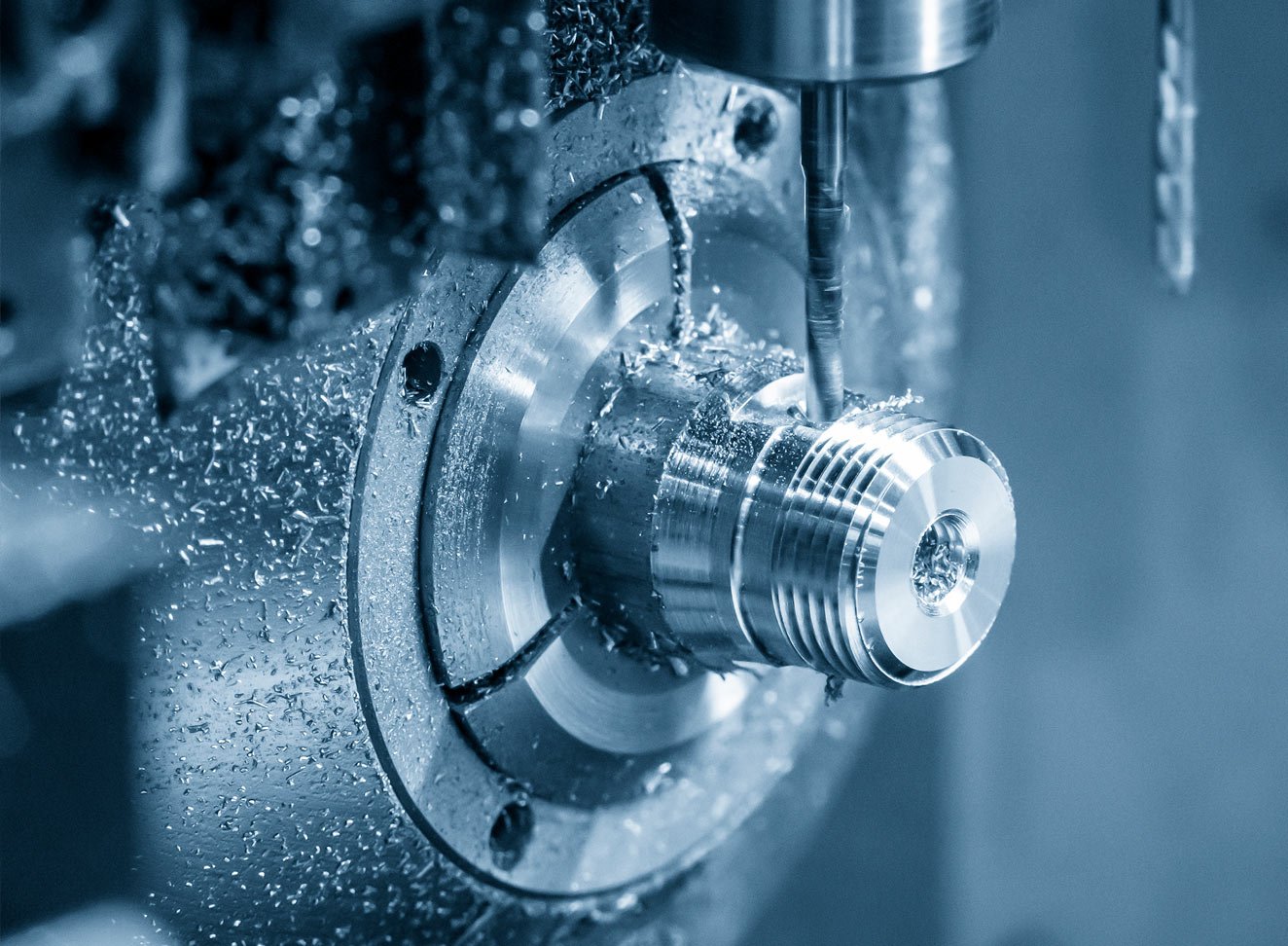
Machine Tools
“Machine tools” serves as the overarching term encompassing any tool capable of performing a process on a workpiece, typically involving cutting. These tools come in various forms depending on the type of CNC machine in use. For instance, CNC lathes employ stationary tools while moving the spinning raw material into the tool to execute cuts. Conversely, CNC mills move spinning tools into stationary material.
However, the advent of more advanced 5-axis machines allows for simultaneous movement of both the tool and the workpiece. This capability enables the creation of more intricate features in the finished part.
Machine tools are commonly stored in “tool libraries,” which are machine racks designed to house all the tools necessary for machining a part. An automated tool changer is responsible for removing a tool from the spindle, placing it in the tool library, and subsequently installing the next tool.

Headstock
The headstock, exclusive to lathes, houses the primary drive, bearings, and gears necessary for rotating the chuck at the prescribed speeds for machining. Positioned on the left-hand side of a CNC lathe, the headstock is typically enclosed and can be accessed through removable inspection panels.
Chuck
The chuck is a lathe-specific component utilized to securely hold the raw material during machining operations on a lathe. It is rotated at high speeds by the spindle. Typically, a chuck features three or four pneumatically or hydraulically actuated grips. Three-jaw chucks possess self-centering grips, where all grips move radially simultaneously.
In contrast, the grips on four-jaw chucks can be individually adjusted and are not self-centering. Four-jaw chucks offer higher accuracy compared to their three-jaw counterparts and enable eccentric cutting by precisely controlling the grip positions to accommodate any variations in the raw material.
Machine Bed
In a CNC mill, the machine bed serves as the platform for mounting the raw material. Work-holding jigs of different types are employed to securely clamp the workpiece in position. The bed typically features t-slots or holes to facilitate attachment of the jigs. Traditional CNC machine beds allow movement only along the horizontal x- and y-axes, whereas more sophisticated 5-axis machines can incorporate rotational motions along the x- and y-axes as well.
Tailstock
The tailstock is an essential component of a CNC lathe, providing axial support to long, cylindrical workpieces on one end while the chuck supports the other end, simultaneously rotating the material. Without the tailstock, the cutting forces could cause the material to deflect away from the cutter.
The tailstock quill, which spins freely inside the tailstock, is centered above the raw material. This feature proves particularly advantageous for machining components like power screws or shafts. The tailstock movement is restricted to the lathe’s z-axis to accommodate varying lengths of raw material.
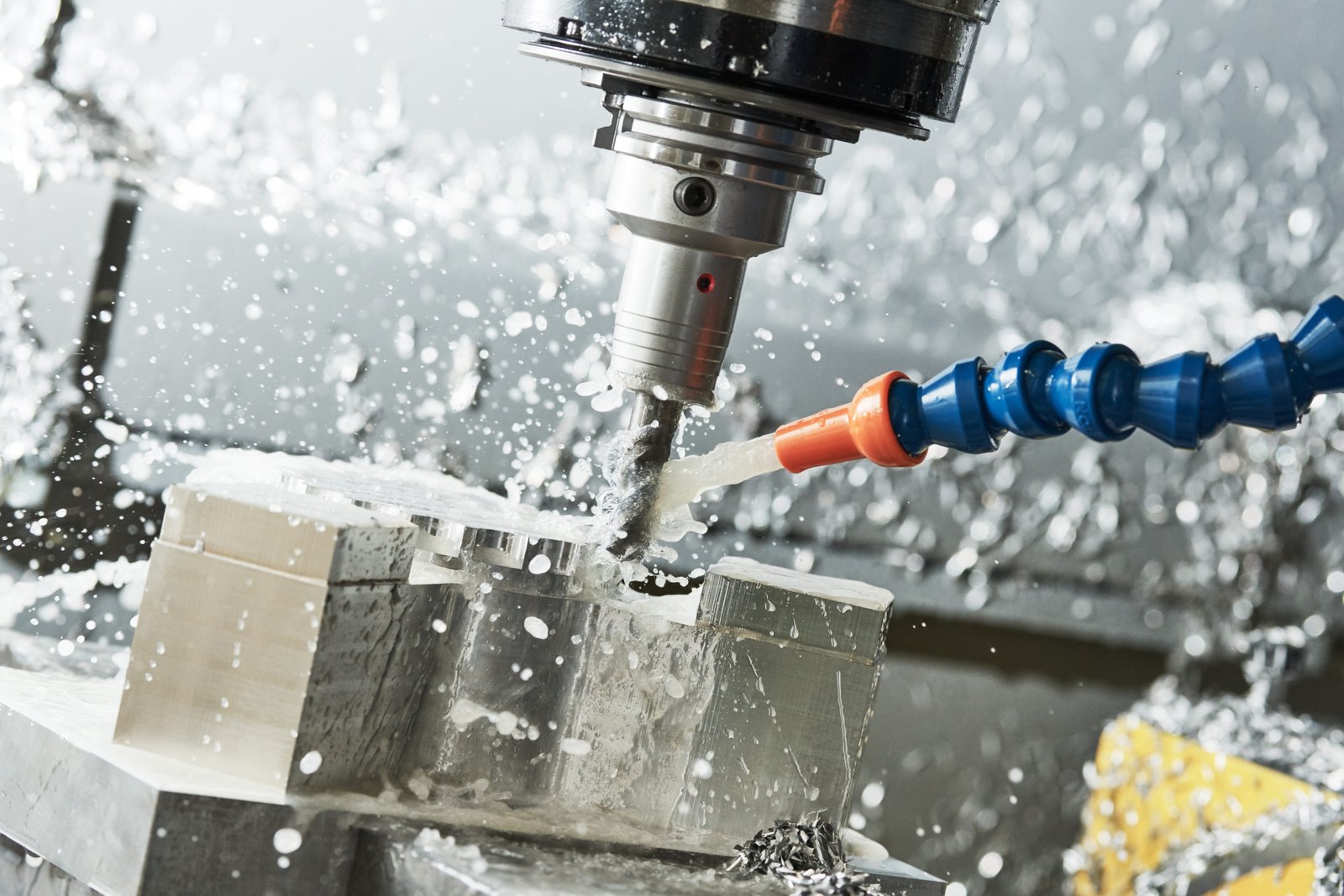
Coolant tank
To mitigate the excessive heat produced during machining and prevent damage to the machine tool or workpiece, coolant is pumped from the coolant reservoir and applied to the part undergoing machining.
How to Clean Parts of a CNC Machine
Spindle and Chuck
- Switch the machine off and unplug the electricity.
- Use a brush to remove chips and debris from the spindle and chuck.
- Wipe down surfaces with a clean cloth dampened with a mild cleaning solution.
- Take note of any wear or damage indicators.
Tool Holders
- Take the tool holders out of the apparatus.
- Clean holders with a brush to remove debris and coolant residue.
- Wipe down with a cloth dampened with cleaning solution.
- Check for any signs of damage or excessive wear.
Guideways and Rails
- Inspect guideways and rails for debris or buildup.
- To get rid of loose particles, use a vacuum or compressed air.
- Wipe down surfaces with a cloth dampened with cleaning solution.
- Use lubrication according to the manufacturer’s recommendations.
Coolant System
- Drain coolant from the system according to manufacturer guidelines.
- Clean coolant reservoir and filters.
- Refill with fresh coolant.
- Inspect connections and hoses for damage or leakage.
Control Panel
- Switch the machine off and unplug the electricity.
- Wipe down control panel surfaces with a clean, damp cloth.
- Avoid using excessive water or cleaning solutions near electronic components.
- Inspect buttons and switches for proper operation.
Chip Trays and Enclosures
- Remove chip trays and clean out accumulated chips and debris.
- Wipe down trays and machine enclosures with a cloth dampened with cleaning solution.
- Inspect for any signs of damage or wear.
Linear Encoders
- Gently wipe down linear encoders with a soft, dry cloth to remove dust and debris.
- Avoid using cleaning solutions that may damage sensitive components.
- Check for any signs of misalignment or damage.
Safety Shields and Covers
- Remove safety shields and covers as necessary.
- Use a towel dipped in cleaning solution to wipe clean.
- Ensure shields are securely reinstalled after cleaning.
Inspect and Test
- After cleaning, inspect all parts for cleanliness and proper functioning.
- Test machine operation to ensure everything is functioning correctly.
- Address any issues or abnormalities discovered during the cleaning process.
Conclusion
Overall, MaTec Vietnam has just introduced you to the parts of a CNC Machine and how to clean them. With the knowledge we have provided, we hope you gain a better understanding parts of a CNC Machine for optimal efficiency. Additionally, if you want to read more about CNC Machining, you can refer to the following article: What is Precision Machining?