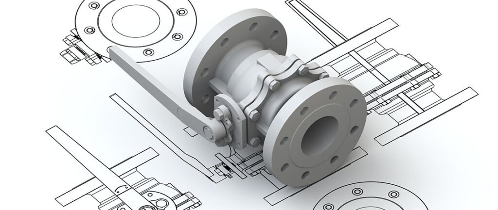
Preparing CAD files for CNC cutting is a crucial step in the manufacturing process, ensuring precision and accuracy in the final product. Computer-Aided Design (CAD) files serve as the blueprint for CNC (Computer Numerical Control) machines, dictating the exact specifications and dimensions of the desired components or parts.
However, transitioning from CAD design to CNC machining requires careful consideration of various factors to optimize efficiency and minimize errors. In this articles, MaTec Vietnam will help you learn how to prepare CAD files for CNC cutting
What is CAD?
Computer-Aided Design (CAD) for Computer Numerical Control (CNC) machining is a specialized software application tailored to the needs of engineers, machinists, and designers involved in the manufacturing process. CAD for CNC machining serves as a vital tool for creating precise digital representations of parts, components, or products, which are then translated into machine-readable instructions for CNC machines.
CAD software for CNC machining offers a comprehensive suite of features and functionalities designed to optimize the design-to-manufacture workflow:
- Geometry Creation: CAD software allows users to create intricate 2D sketches or 3D models of parts or components using a variety of drawing and modeling tools. These tools enable the creation of complex geometries, including curves, surfaces, and solids, with precise dimensions and tolerances.
- Dimensioning and Annotation: CAD applications enable users to annotate their designs with dimensions, notes, symbols, and other annotations to convey critical information to machinists and ensure accurate manufacturing.
- Parametric Modeling: CAD systems support parametric modeling, allowing users to define and control design parameters, constraints, and relationships. Parametric modeling enables the creation of intelligent, customizable designs that can be easily modified and adapted to meet changing requirements.
- Assembly Design: CAD software facilitates the assembly of multiple components or parts into complex assemblies, enabling designers to visualize how individual parts fit together and interact within the final product.
- CAM Integration: Many CAD applications seamlessly integrate with Computer-Aided Manufacturing (CAM) software, allowing designers to generate toolpaths and machining instructions directly from their CAD models. This integration streamlines the transition from design to manufacturing and ensures consistency between the digital model and the physical prototype.
- Simulation and Analysis: Some CAD packages offer simulation and analysis tools to evaluate the performance, functionality, and manufacturability of designs. These tools enable designers to identify potential issues, such as interference, collisions, or material constraints, and optimize their designs accordingly.
- File Export Formats: CAD software supports a wide range of file export formats, including standard formats like DXF and DWG, as well as proprietary formats specific to CNC machine controllers. These export options ensure compatibility with CNC machines from various manufacturers and enable seamless data exchange between design and manufacturing systems.
The Use of CAD and CAM in CNC Machining
The utilization of CAD and CAM in CNC machining represents the prevailing method for generating code for CNC machines, surpassing alternative approaches in popularity.
The process initiates with the creation of a 2D drawing or 3D model of a component using CAD software such as AutoCAD or SketchUp. Subsequently, the workflow progresses through the following steps:
- The model is then imported into CAM software, specialized in automating the manufacturing process.
- Notably, integrated CAD/CAM software solutions like SolidWorks and Fusion 360 streamline both CAD and CAM functionalities. Activation of the built-in CAM capabilities is simplified; in Fusion 360, users switch the workspace from ‘Design’ to ‘Manufacturing,’ while in SolidWorks, the SolidWorks CAM add-in is opened.
- Users proceed by selecting the CNC machine, cutter, and coordinate system.
- A manufacturing sequence, referred to as an operation plan in SolidWorks, is created.
- The software is prompted to generate a toolpath.
- A simulation is conducted to ensure alignment between the operation plan, toolpath, and machine shop practices.
- The G-code file, essential for post-processing, is generated and saved. It’s crucial to select a post processor compatible with the CNC machine, as it translates the code into the machine’s specific conventions. These machine-specific processors leverage libraries containing machine-specific controls. While many CNC machines include their CAM systems, they also support conventional CAM software.
- Finally, the file is imported into the CNC machine for machining.
It’s noteworthy that contemporary CAM software can autonomously detect design alterations and update the NC program accordingly, underscoring the advantages of CAD/CAM integration.
In essence, the synergy between CAD/CAM software and CNC machines, augmented by computer-driven feed drives, empowers the creation of virtually any 3D shape, exemplifying the versatility and efficacy of modern manufacturing technologies.
Considerations in CAD Design for CNC Machining
When embarking on a design for CNC machining, the initial step involves utilizing CAD software, setting the groundwork for subsequent stages. CNC machining operations often entail higher costs compared to alternative manufacturing processes, necessitating careful deliberation to save both time and expenses.
Hence, several factors merit consideration during the design phase to tailor the design to a specific machining process, thereby enhancing efficiency and cost-effectiveness. These considerations also underscore the importance of collaboration between designers and machinists.
These CAD design considerations, commonly referred to as design-for-machining rules, encompass the following aspects:
Tolerance Optimization
Geometric dimensioning and tolerancing (GD&T) provide machinists with essential control and flexibility downstream. Achieving precise features, such as drilling holes, necessitates correct sizing, positioning, and shaping, typically defined by nominal dimensions and annotations.
However, exact precision is impractical and often requires additional operations, thereby slowing down the machining process and increasing costs. Consequently, tolerances, delineating allowable variation from nominal dimensions, must be optimized considering various factors such as tool change schedule, tool compensation capabilities, part geometry, fixture supports, and tool guiding jigs.
Collaboration between designers and machinists is pivotal to grasp the significance of these factors.
Material Selection
The choice of material significantly influences machining quality, costs, and operational parameters like tool materials, motor power, cutting speeds, tolerances, and surface finishes. Apart from machining considerations, material selection should also account for chemical and physical properties and functional requirements beyond machining.
Feature Minimization
Machining should be limited to features necessitating tolerances that other manufacturing processes cannot achieve. Typically, machining is reserved for features requiring dynamic balance, press fitting, locating, locking, bearing, or close dimensional tolerances for subsequent assembly considerations.
Whenever possible, reduce the number of machined features through alternative methods like undercutting, chamfering, or casting in holes, particularly if specified tolerances permit.
Stock Allowance Minimization
Efforts should be made to minimize the material to be machined away to produce the final part, known as stock allowance. Failure to do so increases costs associated with tool replacement, material wastage, and machining time. Optimizing dimensions based on the size of material loaded into the CNC machine facilitates stock allowance minimization.
Feature Standardization
Standardize features whenever feasible, such as selecting hole diameters from a limited range of sizes and limiting the number of different diameters in a single part.
Surface Finish
The desired surface finish dictates the machining operation employed. However, certain operations like diamond turning, precision grinding, lapping, and honing can achieve small surface finish tolerances but at increased machining costs.
Strength and Stiffness
Ensure that the part possesses adequate strength and stiffness, particularly in loading directions, to withstand cutting forces and prevent undesirable effects like breakage, bending, deflection, or unstable vibrations generated by powerful CNC machine motors.
Accessibility
Feature locations should be easily accessible with standard machining tools to avoid the need for specialized tooling, which may incur additional costs and limit allowable tolerances due to unstable vibrations or deflections.
Preparing CAD Files for CNC Machining
Upon finalizing the product design process, encompassing conceptualization, synthesis, analysis, evaluation, and documentation, the CAD files is forwarded to the machinist for CNC machining.
While machinists need not grasp the intricacies of product functionality – a task reserved for engineers or designers – several key considerations must be addressed in preparing CAD files for CNC machining.
Remove Unwanted Layers
Dimensions and notes, while aiding machinists in visualizing and understanding parts, serve as supplementary information and do not directly contribute to part creation. Therefore, it’s imperative to eliminate these informational elements from the CAD files to streamline CNC machining preparation.
Choose the CNC Machine
Most CAD/CAM programs facilitate the addition of CNC machines to the database, allowing customization of settings to match machine capabilities.
Machinists must specify the exact machine to be utilized during CNC file preparation, ensuring alignment with the envisioned machining process defined by the designer.
Assign Machining Data
Machining data encompasses cutter types, sizes (diameter and length), and the number of roughing and finishing passes. This data, when assigned, is encoded into the G-code, guiding the CNC machine during machining operations.
Some machines feature built-in tool databases, eliminating the need to assign tool data but necessitating cutter loading prior to machining.
Undertake Element Sequencing
When working with 2D or 3D wireframe geometries, element sequencing is crucial. CAM software perceives geometric components as mere lines or arcs, necessitating manual sequencing to dictate the machining order and cutter placement. However, solid models are automatically sequenced by the software, generating an operation plan outlining the necessary toolpath steps.
Run Simulation
Conducting a simulation enables machinists to assess the compatibility of the generated operation plan with shop capabilities. Any discrepancies can be rectified within the CAM software to ensure alignment with shop practices, thereby minimizing errors, waste, and associated costs.
Post Processing
Post processing involves converting toolpath data (TPD) into machine-specific numerical control (NC) code. While TPD is machine-independent, the generated code must adhere to the conventions of the selected CNC machine. Therefore, selecting an appropriate post processor tailored to the specific machine’s requirements is essential for seamless CNC machining execution.
Best Practices for CNC Machining Preparation
Thoroughly Review the Technical Drawing
Careful examination of the engineering/technical drawing allows for the identification of potential issues and inconsistencies in dimensioning and tolerancing. Any discrepancies can be addressed by seeking clarification from the designer or requesting revisions to ensure accurate machining.
Studying the drawing also aids in visualizing the model, providing insight into the designer’s intentions. Utilizing CAD/CAM software facilitates visualization, simplifying the interpretation process. Additionally, identifying the datum, a reference axis or surface, is essential for precise measurements and machine operations, particularly in cases where multiple datums are present.
Understanding the number of parts outlined in the drawing assists in determining tooling requirements and establishing material type and raw stock size, thereby minimizing excessive stock allowances.
Understand Design and Functional Priorities
Design priorities dictate the machining sequence, while functional priorities determine the importance of a part’s features. Together, they inform decisions regarding part positioning, machining sequence, and measurement techniques.
Ensure Comprehensive NC Code Generation:
The NC code comprises commands instructing the machine on various operations, denoted by prefixes such as G, M, F, T, S, and N. Utilizing these prefixes ensures that the NC code encompasses all necessary operations, including motion, feed rate, and utility functions like tool changes.
While CAM software simplifies NC code generation, it’s essential to review and understand the generated code for accuracy and make necessary modifications. Optimizing the code minimizes manufacturing downtime by eliminating unnecessary movements and tool changes, enhancing efficiency and cost-effectiveness.
Optimize Program Efficiency
Inefficient programs can lead to increased manufacturing costs and downtime. Optimizing the program involves eliminating unnecessary movements and tool changes. CAM software with built-in editors, like MasterCAM, facilitates code editing and comparison, enabling efficient program optimization.
Provide Clear Instructions for CNC Operators
Clear and detailed instructions for CNC operators ensure smooth execution of machining operations. Embedding remarks within the program and incorporating notes on shop/technical drawings guides the inspection and testing process, enhancing operational clarity and efficiency.
>>> Read more: How to Become a Professional CNC Programmer
Conclusion
Overall, preparing CAD files for CNC machining is a meticulous process that involves several key steps and considerations. By carefully reviewing technical drawings, understanding design priorities, ensuring comprehensive NC code generation, optimizing program efficiency, and providing clear instructions for CNC operators, machinists can streamline the machining process and enhance overall efficiency and accuracy.